2019-04-26

Evolution of the FunCPU Homebrew CPU Hardware


Here is the front panel as it was originally planned:


The original interface is described here.

This is how actually version 1 looked like...


More details are available here .Below one can see the modules of version 1 scattered all around the floor in the course of unit testing.


It was my first attempt, and resulted in a rather chaotic design and implementation. It is needless to say that it was not working. It almost worked, but not quite. I created a new version. Version 2 had to be rebuilt it from scratch, using a little more reliable and disciplined approach. 

This is how the front panel of version 2 looks like:


One can immediately recognize that in terms of the visual appeareance I have returned back to the original concept. More or less....

It is constructed from four modules plus the control board, using 74HC components and 4 EPROMs (3 used for micro-sequencer and one for the tokenizer for the tagged architecture) and one 32K SRAM. The modules are stacked one on another. They are interconnected via 3 buses each with 40 pins. Here one can see the stacked boards. 


Please notice that testing can be done just by looking at the 120 exposed pins. These pins more or less describe the full behaviour of the CPU at any moment in time. Approximately 30 ICs were used for the CPU itself, and another 15 ICs were required to implement the interface. (These 45 components include the ROMs and RAM as well). This is needed to communicate with the CPU, i.e. to enter and read data.

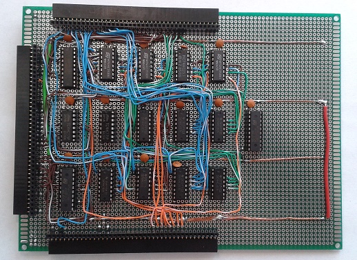
Here is the register module of the second build: 


2015-11-13

Debugging FunCPU control board

A couple of months have passed till I could eliminate a long-standing issue. After making minor modifications to the control board, and also improving the RAM/ROM module the whole thing has stopped working. Voltage level dropped to about 2.0 V. I have almost given up, since I did not have a clue what was causing this problem. I checked, doublechecked and triplechecked all boards, all connections in vain. 

I have spent hours and days to resolve this issue. Finally, I took everything apart. Extended the tester module to give additional control signals for the clock generator. I connected the RAM/ROM, the clock generator and the test modules. Ok, it worked fine. Then, I started adding more boards...

But no signals could be detected at the control board. This was due to some bad wiring, leaving out ground signals. Ok, added ground signals. Almost everything was connected and it was still working.


But when I have plugged the address/control switch bus (bus 5), the clock faded. I tested it wire by wire to find out that again a power line (bad soldering) and  ground signal were responsible for this. Finally, it worked just fine, the clock, the RAM/ROM, the control board together. 

Then, I have added the ALU and register modules. So everything is interconnected as depicted in the picture below and the whole thing is just working fine. At least it seems to be working. I still need to test ALU and  register modules being conntected. Once it is done, I could continue with the finishing touches. Basically I just need to add some EPROMs (with micro-programs) and some control logic.


2015-06-27

FunCPU - Testing ALU and Register modules

The vast majority of FunCPU has been completed. Static modules (ALU and registers) are being verified now. The image below shows three modules interconnected. The upportmost is the test module. In the middle one can see the register file, and on the bottom the ALU can be found.


Once static function has been verified, the micro-sequence can implemented and connected to these modules. Numerous tests are to be performed to check if everything is working as expected. Applying different setup conditions defined by the 6 DIP switches mounted on the test-board (note: an additional bus must have been added to the test module.) I can check each register and ALU function by observing the ALU or register output connected to the LED bars on the test module. 

The following basic cases have been identified:
  • RI_SET (this is tricky, as first DI must be incremented, then cleared)
  • DI_CLR_, DI_SET_, DI_INC - clear, set and increment DI respectively.
  • SI_CLR_, SI_INC - clear and increment SI respectively.
  • V_CLR_, V_SET - clear and set V respectively.
  • S_SET, S_CLR - again for set and clear operation executed on S.
  • SCZ_SET, SCZ_CLR - same for the SCZ register.
  • AC_INC, AC_SET - increment and set argument counter respectively. Special care must be taken to check the working of argument counter flag.
  • FI_SET_, FI_INC - setting and incrementing of function index register.
  • V register must be tested against different ALU setup (decrement, identity and increment modes).
  • Address multiplexer should generate address signals as designed one of the following sources: SI, DI, FI, SI+V'. The last one is an integration test, involving ALU operations.
The following buses will be used for input for register module:
  • B10 to provide power supply, classification information and raw 8 bit data.
  • B11 to supply most of the control signals (including the two-phase clock) to be generated by the micro-sequencer.
  • B12 to transfer additional control information also determined by the micro-program.
The following buses will supply input for the test module:
  • B9 - transferring the 7 bit result (MSB is preserved).
  • B13 - displaying the 8 bit address.
  • B14 - supplying status, classification and argument counter zero flag to micro-sequencer.
  • B16 - containing the full 8 bit result of the ALU operation. 


In addition to that, of course register and ALU modules are interconnected as the image above also reveals.


2015-05-23

FunCPU - Internal States and State Diagram


State
Encodedin binary
Explanation
init0000Initial, starting state. FunCPU remains in this state until it determines the lenght of the input expression
start0001Start phase is entered upon each reduction cycle. FunCPU decides if the expression is reduced, or the reduction process should continue.
copy0010In this state FunCPU copies one symbol after another from the source expression to the target.
inc0011Increment function is being executed.
dec0100Decrement function is being executed.
if-in0101if-then-else function is found. If the condition is constant, then the appropriate branch state is reached.
if-then0110Condition was true, the "then" part is selected.
if-skip-else0111Condition was true, the "else" part must be ignored.
if-else1000Condition was false, the "else" part must be selected.
if-skip-then1001Condition was false, the "then" part is ignored.
func-in1010User defined function entry. In this state the FunCPU checks, if all the arguments are available as constant, thus the function can be executed. Otherwise the function reduction is postponed.
func-copy1011FunCPU is unfolding the function definition and performing argument binding.
err-iin1100Some unexpected condition is encountered, most probably due to some hardware error or error in micro-program. Program execution is aborted.
err-arg1101Function with less argument is found, than expected. Program execution is aborted.
err-empty1110Empty expression or function definition is found. Program execution is aborted.
stop1111Input expression has been succesfully calculated. The processor will idle its final state and the result value is observable by looking at the data LEDs.


2015-04-18

FunCPU - Registers

The register file module has been completed as it is shown in the picture below. Please refer to architecture concept for an overview of registers and overall architecture.


It comprises the following registers:
  • RI (redex index) is implemented as a 74HC273 and used to store temporary the destination index value during function reduction. If a function cannot (yet) be called (because some of its arguments are not yet available. i.e. they are not constants), then reduction reverts to the target position defined by this index.
  • DI (destination index) is composed of two four bit registers using two 74HC161 chips. This holds the value of the destination register. This value can be stored temporary to and restored from RI.
  • SI (source index) is implemented in similar fashion, it stores the source index, it is selected to read the current symbol of source expression.
  • FI (function index) is also implemented similarly with two counters, it stores the function index, which is used to read/map the function definitions.
  • AC (argument counter) is implemented with a single 74HC161 chip. This acts as the argument counter to facilitate argument interpretation and handling. Note: this counter is slightly differently used as originally proposed to save parts and reduce complexity. This is also an up-counter, with the twist, that the binary value 1111 represents the "zero" value. Applying this encoding, the zero value can be detected by looking at the TC flag output.
  • V (value register) is implemented as a 74HC273. This register is used analogously to the accumulator of a traditional CPU (mainly accumulator machines). Calculated values are fetched to and from here between the memory and ALU.
  • S (state register) employs a 74HC175 to store processor state. This is a four bit value, 0000 represents initial state, whereas 1111 is the final state, when computation is finished and result is available. This register is refreshed, whenever a state transition is required, as governed by the micro-code.
  • SCZ - serves two purposes. The lower 3 bits are used to store the symbol classification value, the most significant bit is a flag, which tells whether argument count reached "logical" (recall the strange encoding) zero value. This register is usually refreshed upon restarting the micro-code sequence.


Please note that no register is fully or partially exposed to the programmer. The programming model does not make use of any registers directly. In fact, none of the registers can be manipulated or even accessed explicitly by the user program. All of these registers are, however, manipulated by the micro-sequencer, but it is hidden from the programmer.
Further observations:
  • No conventional PC (program counter) is employed.
  • No stack is present.
  • No nonventional processor state register or even flags (to denote zero, carry, overflow and so on) can be found here.


A small portion of the register module is dedicated to a 4 input multiplexer, which is introduced to select among four different address values. These are as follows:
  • SI - address determined by the source index. Generally used to fetch the next symbol of the expression being reduced.
  • DI - address determined by the destination index. This is selected, if the part of the reduced expression must be stored to the resulting expression.
  • FI - address as defined by the function index. This input is chosen when function definition is being unfolded.
  • Finally, SI + V', which is used when binding argument values in the course of unfolding function definition. Note: in such case SI register points to the next symbol in source expression. Assuming that the function has three arguments: SI-1, SI-2 and SI-3 represent argument 3, 2 and argument 1 respectively. Recall that argument numbers are encoded in two's complement form, therefore by simply adding SI and V' (modified V value holding the argument number in the binary form 1111 11xy) gives us the parameter value to be bounded to the argument in question. 
 
Register board being one of the main boards implements quite a fiew buses.

Bus 10 is utilized to drive data and tag classification signals from the RAM board.
ncncD6D4D2D0C2PWR
GNDncD7D5D3D1C1C0

Bus 11 transfers control signals defined by the micro-sequencer.
V_SETAC_INCCPO_EDSCZ_SETFI_SET_FI_INCDI_SETRI_SET
CLK2V_CLRAC_SET_CLK1S_SETSI_INCCLK_RUNDI_INC

Bus 12 transfer further signals from the micro-sequencer.
ALU_AALU_BncncncADR_SEL_1ADR_SEL_0nc
ncncncncS0S1S2S3


Bus 13 supplies a 8 bit address signal to the RAM module.
A7A6A5A4A3A2A1A0
ncncncncncncncnc

Bus 14 provides the current CPU state, symbol class along with argument counter zero flag (as defined by the S and SCZ registers respectively).
S3S2S1S0SCZSC2SC1SC0
ncncncncncncncnc

Bus 15 supplies two ALU input sources, the SI and the V register.
V7V6V5V4V3V2V1V0
SI7SI6SI5SI4SI3SI2SI1SI0


Bus 16 receives the 8 bit ALU result, which is fed to the address multiplexer.
R7R6R5R4R3R2R1R0
ncncncncncncncnc

Finally, bus 17 is used to pass some control signals together with argument counter and power supply lines to ALU.
ALU_AALU_Bac3ac2ac1ac0CPWR
GNDncncncncncncnc